今回はArduinoで自動コイル巻き機を試作したのでご紹介。
巻きあがりのクオリティはこんな感じ。
折り返しのタイミング設定をミスって左端がちょっとダブついてしまったが全体的にかなり密に巻けているのでいい感じ。
動作の様子を動画に収めてみた。(音無し動画)VIDEO youtu.be
構成はこんな感じ。
巻き数指定用のボタンはピン数の節約のため5V・GNDのほかにはアナログInput 1つで対応している。
こちらのサイトを参考にさせていただいた。感謝。synapse.kyoto
当初コイル巻き機を思いついた際はコイル芯となるボルトを回転させるモーターはレゴモーターを想定していた。
なぜかというと、細いモーターシャフトからボルトをがっちり掴むようなものを作る案が無かったから。
ただそれだとレゴマインドストーム本体からモーターを動かす必要があり、Arduinoとの連携が面倒くさい。ボタンで回転検知する方式で考えていたけど、結局シャフトカプラーやシャフトフランジというパーツを知ったことでボルトホルダーの課題が解決し、最終的にNema17という規格のステッピングモーターに落ちついた。
今回使ったのもの。
あとインサートナットの挿入補助具として六角スペーサー類。
意外と真鍮のM3ネジの出番が多かった。
その他、ボルトの反対側の軸受け用にダウエルピンとベアリングを買ったけど、意外と片側だけでしっかりホールド出来てしまったのでいまのところ余らしている。仕上げの段階では使おうと思う。
ボルトホルダーはこんな感じでモデル&スライス。
プリントしたものにインサートナットを差し込む。その際、ネジ付きの六角スペーサーをねじ込んだ状態でハンダゴテで挿し込むと1発で上手く行った。
このあたりのテクニックは以下の記事を参考にさせていただいた。感謝。burariweb.info
あとはフランジにダウエルピンを挟んで3Dプリントパーツをネジ止め。
木の端材にタケノコドリルで9ミリ穴を空けてボールベアリングをはめ込んで反対側の軸受けとする。
こんな感じで作ってみた。まぁ今回の試作では右だけでホールド出来てしまったんだけども。
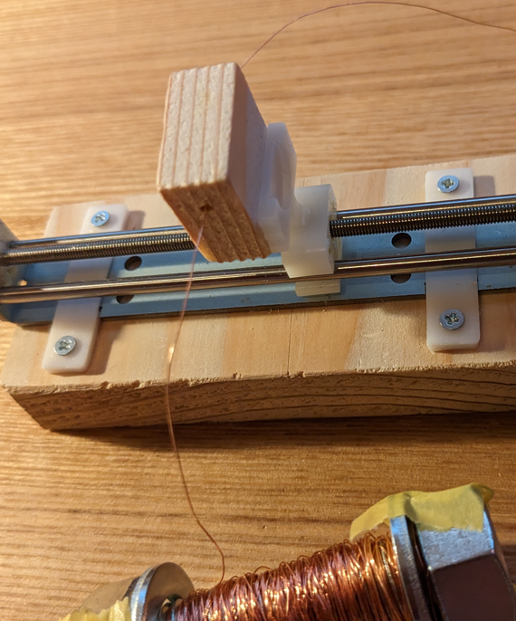
さてこちらは前回紹介したリニアスライディングテーブル。
これも結構曲者で、スライド部についてるのは謎の突起のみ。また座面の固定用と思われる穴はスライド用のガイドが邪魔をしてネジが入らず、知恵の輪状態。仕方ないので別途固定具をモデリングして印刷した。
スライド部は木片に穴をあけて突起に挿し込む作戦。
このままだとグラつくしハズレそうということで、上から別の固定具を被せる。
ほんとに被せてるだけだけど、うまく固定できた。
さて、機械部分はそんなところで、あとは配線とコーディング。
まずは7セグ稼働用の部分だけど、配線はこんな感じで電源は別としてデータ通信にはコントローラーがA0のみ、表示器がD2・D3・D4ピンを使う形。
コードはこんな感じ。
#include <LEDDisplay74HC595.h>
const int sclkPin = 2 ;
const int rclkPin = 3 ;
const int dioPin = 4 ;
int digits [] = {0 ,0 ,0 ,0 };
int cnt = 0 ;
LEDDisplay74HC595 ledDisplay (sclkPin, rclkPin, dioPin);
void setup () {
ledDisplay.refresh (0 ,0 );
}
int judge_button_from_voltage (int voltage) {
switch (voltage) {
case 0 ... 300 : return -1 ;
case 301 ... 550 : return 0 ;
case 551 ... 700 : return 1 ;
case 701 ... 780 : return 2 ;
case 781 ... 850 : return 3 ;
default : return -9 ;
}
}
void loop () {
while (analogRead (0 )>850 ){ledDisplay.refresh (cnt, 0 );}
int button = judge_button_from_voltage (analogRead (0 ));
if (button>=0 ){
if (digits [button]<9 ){digits [button]++;}else {digits [button]=0 ;}
cnt = digits [0 ]+digits [1 ]*10 +digits [2 ]*100 +digits [3 ]*1000 ;
}
while (analogRead (0 )<850 ){ledDisplay.refresh (cnt, 0 );}
if (button==-1 ){
cnt = count_down (cnt);
int val = cnt;
for (int i=0 ;i<=3 ;i++){
digits [i] = (val % 10 );
val /= 10 ;
}
while (analogRead (0 )<850 ){ledDisplay.refresh (cnt, 0 );}
}
}
int count_down (int n){
unsigned long time;
while (n>0 ){
time = millis ();
while (millis ()-time <= 1000 ){
ledDisplay.refresh (n,0 );
if (analogRead (0 )<850 ){
return n;
}
}
n = n - 1 ;
}
return n;
}
面倒くさいのが7セグの扱い。
つまり1秒ごとのカウントダウンを作るのも、普通なら1秒のDelayを入れるところ、7セグを使うせいで待ち時間もリフレッシュ命令を出し続けるという処理になっている。
あとは緊急停止用に何らかのボタンが押されるとカウントダウンが止まるようにanalogRead命令も出している。実際にはモーターを動かすので緊急停止処理は必須だ。
次にモーター制御の配線。
まぁ難しいことはモータードライバーがやってくれるので配線はそこまでややこしくならなかった。
コードはこんな感じ。ほんとはクラス使ってステッピングモーターをオブジェクト化したかったけどCPPに詳しくなくてややこしそうだったので今回は構造体で妥協した。
typedef struct {
uint8_t step_pin;
uint8_t direction_pin;
} Stepper;
const Stepper linear_actuator{6 ,7 };
const Stepper bolt_rotator{8 ,9 };
const int enable_pin = 5 ;
int Speed = 800 ;
int cnt = 0 ;
int flag = HIGH;
void setup (){
pinMode (linear_actuator.step_pin,OUTPUT);
pinMode (linear_actuator.direction_pin,OUTPUT);
pinMode (bolt_rotator.step_pin,OUTPUT);
pinMode (bolt_rotator.direction_pin,OUTPUT);
pinMode (enable_pin,OUTPUT);
digitalWrite (linear_actuator.direction_pin,LOW);
digitalWrite (enable_pin,LOW);
slide (85 );
digitalWrite (enable_pin,HIGH);
digitalWrite (linear_actuator.direction_pin,HIGH);
cnt = 0 ;
}
void rotate () {
for (int s=1 ; s <=8 ; s++){
for (int i=1 ; i<=24 ; i++){
digitalWrite (bolt_rotator.step_pin,HIGH);
delayMicroseconds (Speed);
digitalWrite (bolt_rotator.step_pin,LOW);
delayMicroseconds (Speed);
}
digitalWrite (bolt_rotator.step_pin,HIGH);
digitalWrite (linear_actuator.step_pin,HIGH);
delayMicroseconds (Speed);
digitalWrite (bolt_rotator.step_pin,LOW);
digitalWrite (linear_actuator.step_pin,LOW);
delayMicroseconds (Speed);
}
}
void slide (double millimeter) {
int steps = 4 * millimeter * 10 ;
for (int s=1 ; s <=steps; s++){
digitalWrite (linear_actuator.step_pin,HIGH);
delayMicroseconds (Speed);
digitalWrite (linear_actuator.step_pin,LOW);
delayMicroseconds (Speed);
}
}
void loop () {
digitalWrite (enable_pin,LOW);
digitalWrite (linear_actuator.direction_pin,flag);
rotate ();
digitalWrite (enable_pin,HIGH);
cnt++;
if (cnt>=80 /0.2 ){cnt=0 ;flag=!flag;}
}
Nema17が一周する間にリニアスライダーが0.2ミリ移動するコードになっていて、エナメル線の径が0.2ミリなので理論上は隙間なくコイルが巻かれることになる。まぁ、まさかそんなにうまくいかないと思ってたので冒頭で紹介したような精度が出たのは正直驚いた。
さて、別々に開発したコントローラーとモーター制御を融合させたのが次のコード。
#include <LEDDisplay74HC595.h>
const int sclkPin = 2 ;
const int rclkPin = 3 ;
const int dioPin = 4 ;
int digits [] = {0 ,0 ,0 ,0 };
int cnt = 0 ;
LEDDisplay74HC595 ledDisplay (sclkPin, rclkPin, dioPin);
typedef struct {
uint8_t step_pin;
uint8_t direction_pin;
} Stepper;
const Stepper linear_actuator{6 ,7 };
const Stepper bolt_rotator{8 ,9 };
const int enable_pin = 5 ;
int Speed = 800 ;
int cnt2 = 0 ;
int flag = HIGH;
int judge_button_from_voltage (int voltage) {
switch (voltage) {
case 0 ... 300 : return -1 ;
case 301 ... 550 : return 0 ;
case 551 ... 700 : return 1 ;
case 701 ... 780 : return 2 ;
case 781 ... 850 : return 3 ;
default : return -9 ;
}
}
void rotate () {
for (int s=1 ; s <=8 ; s++){
for (int i=1 ; i<=24 ; i++){
digitalWrite (bolt_rotator.step_pin,HIGH);
wait_withRefresh ();
digitalWrite (bolt_rotator.step_pin,LOW);
wait_withRefresh ();
}
digitalWrite (bolt_rotator.step_pin,HIGH);
digitalWrite (linear_actuator.step_pin,HIGH);
wait_withRefresh ();
digitalWrite (bolt_rotator.step_pin,LOW);
digitalWrite (linear_actuator.step_pin,LOW);
wait_withRefresh ();
}
}
void wait_withRefresh (){
unsigned long time = micros ();
while (micros ()-time <= Speed){
ledDisplay.refresh (cnt,0 );
}
}
void slide (double millimeter) {
int steps = 4 * millimeter * 10 ;
for (int s=1 ; s <=steps; s++){
digitalWrite (linear_actuator.step_pin,HIGH);
wait_withRefresh ();
digitalWrite (linear_actuator.step_pin,LOW);
wait_withRefresh ();
}
}
void setup () {
ledDisplay.refresh (0 ,0 );
pinMode (linear_actuator.step_pin,OUTPUT);
pinMode (linear_actuator.direction_pin,OUTPUT);
pinMode (bolt_rotator.step_pin,OUTPUT);
pinMode (bolt_rotator.direction_pin,OUTPUT);
pinMode (enable_pin,OUTPUT);
digitalWrite (linear_actuator.direction_pin,LOW);
digitalWrite (enable_pin,LOW);
slide (85 );
digitalWrite (enable_pin,HIGH);
digitalWrite (linear_actuator.direction_pin,HIGH);
cnt2 = 0 ;
}
void loop () {
while (analogRead (0 )>850 ){ledDisplay.refresh (cnt, 0 );}
int button = judge_button_from_voltage (analogRead (0 ));
if (button>=0 ){
if (digits [button]<9 ){digits [button]++;}else {digits [button]=0 ;}
cnt = digits [0 ]+digits [1 ]*10 +digits [2 ]*100 +digits [3 ]*1000 ;
}
while (analogRead (0 )<850 ){ledDisplay.refresh (cnt, 0 );}
if (button==-1 ){
count_down (&cnt);
int val = cnt;
for (int i=0 ;i<=3 ;i++){
digits [i] = (val % 10 );
val /= 10 ;
}
while (analogRead (0 )<850 ){ledDisplay.refresh (cnt, 0 );}
}
}
int count_down (int *n){
unsigned long time;
while (*n>0 ){
stepping ();
ledDisplay.refresh (*n,0 );
if (analogRead (0 )<850 ){
return 0 ;
}
*n = *n - 1 ;
}
return 0 ;
}
void stepping () {
digitalWrite (enable_pin,LOW);
digitalWrite (linear_actuator.direction_pin,flag);
rotate ();
digitalWrite (enable_pin,HIGH);
cnt2++;
if (cnt2>=40 /0.2 ){cnt2=0 ;flag=!flag;}
}
これもモーターの移動中に7セグのリフレッシュが必要だったり、けっこう面倒くさいコードになったけどとりあえずうまく動いてくれた。
最後の方かなり雑な紹介になったけども、眠たくて気の利いた締めも思いつかないのでこれにて。


 10個入り")


電動 ボールグリップ ドライバー ビット1本付 電ドラボール 220USB-1 & プラス・マイナスビット 5本組")


